Monday, May 31, 2010

The Maggie Interface

While the grown-ups were off in Wisconsin for the SALT Board Meeting, some of us wrote boring SPIE papers while others sought to make the clean room a better place - breaking exciting ground in high-tech instrumentation development.  Enter: the latest must-have Faro Arm accessory... the all new, hands-free, Maggie Interface! 


The teat of the dummy has a switch built into it & contact is made by doing what Maggie Simpson does best! The number of readings to be taken can be set by the user & the counter talks to the Faro software to do the rest.


Although the Faro's burst mode saves you having to use the obnoxious green button on the Arm to take readings, you almost always need someone else parked next to the laptop to keep a finger on the insert key.


Now this option lets you work on your own, even in those hard to reach places...  In fact, it's best to work alone if you're going to use this as colleagues tend to spend a lot of time making fun of you!


Sometimes we wonder if this year in the clean room may have done us irreparable damage, & sometimes we just know...


Now, if only Francois would finish working on the ALIGN button for the SAC, then we could all go home!

Thursday, May 20, 2010

M3's Gooood!!

After quite a bit of fiddling around, we eventually got fringes with the big CGH!  Pretty good ones at that, so this is Huge: it means there's nothing wrong with the surface figure of M3 :) :) :)


We've now confirmed that the mirror surfaces are all fine & 3 of the 4 have been aligned - we just need to align M3 to the rest of them now...

Tuesday, May 18, 2010

Fisheye Day in the clean room :)

It's great to be back & Extremely good to be reunited with my weapon of choice!  Some fun with the fisheye lens served as a peace-offering to counter any abandonment issues my camera may have developed while I left it with Darragh these past few days... 


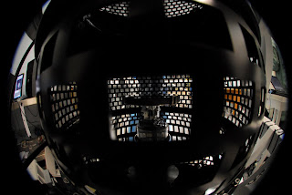
Here's a mangled view of the interferometer sitting on top of the NRS simulator super-structure.


& the CGH spied through one of the holes for the SAC over-pressure fan hoses.


A new slant on geometrical optics...


Ok CGH - Sit... & Stay!


Here the CGH was being illuminated from above with a LED flashlight.


From this angle you can see the CGH's titanium base reflected in M3.


This one's a mind-bender...  Looking down into the SAC with a fisheye you see the pizza pan (M4's intermediate mount structure), the underside of the super-structure platform & the photographer reflected in M5.  Then through the hole in M5 you see part of the M2 cage, M2's image of the CGH (complete with the camera lens reflected in the CGH) on M3, the outer edge of M3 & the CGH!


From this angle you get to see the interferometer & camera reflected in M5, & the reticle of the coat hanger centred in the hole in M5.


Similar to the pic above, but taken with a flash.  Note the blast of green light being thrown off by the CGH down in the hole in M5!


Here's a zoomed in look at M3 & the CGH from above - again the flash hitting the CGH produces some gorgeous effects & the camera itself's niftily reflected in the CGH - & don't forget, the whole lot's imaged by M2 onto M3 & & &...


Much the same as the previous shot, but taken with the camera off axis so the rainbow beams fired off by the CGH seem to bounce around wildly inside the SAC.


So SO cool!! :)

Friday, May 14, 2010

Getting the CGH aligned

Now that the CGH is in place, it has to be positioned to within 25 microns in decentre, about 70 microns in despace & less than 10 arcseconds in tip & tilt...  As always, a cunning plan is required & fortunately we hardly ever leave home without one ;)

First of all, the M4 "steering wheel" - the bit that can be removed & replaced repeatably - has to be removed to allow the alignment telescope on the platform to see the CGH & the coat hanger below.


The alignment telescope looks down via a fold-mirror - which too is repeatbly replaceable as it needs to get out of the way whenever the interferometer's in use.


By adjusting the focus of the alignment telescope, it's possible to find the centroids of the 4 features we need to get the CGH aligned to the coat hanger (which marks the optical axis of the SAC) in both decentre & tilt.


First we focus on the coat hanger reticle & find the coordinates for the centre of the cross, which was meticulously set up previously to coincide with the optical axis of the SAC.


Next, we centroid the image of the alignment telescope's auto-reflection target as it bounces off the coat hanger reticle. 


The coat hanger (which also locates repeatbly) is then moved out of the way to allow the alignment telescope to access the CGH.  The auto-reflection target image from the CGH is centroided & those coordinates compared to the coat hanger's.  Adjustments are made with the tip & tilt actuators on the CGH until the coordinates match.


We then focus on the cross etched on the surface of the CGH & compare the coordinates of its centroid to those of the coat hanger cross.  The necessary adjustments are made with the X & Y actuators on the CGH mount.


It all sounds simple enough in principle, but by now we ought to be used to the fact that procedures like this end up being iterative & thus take Time & Loads of patience!

Wednesday, May 12, 2010

Inserting the big CGH!!

Exciting day in the clean room - time to install the big CGH!  First the rails for putting M3 back had to be set up again.


Then the mirror was lifted out of its box & lowered onto the rails.


M3's cover was removed: Ooooh - VERY Shiny! :)


Next, on went the new 2-part perspex cover with a hole for the CGH mount...


Then the CGH lifting jig was lowered into position with the hoist.


& inserted through the hole in the cover & M3 - taking care to feed the actuator cables all the way through as well.


Once in place, the CGH installation jig could be removed.


Who could resist taking the cover off the CGH at this point?!


Still the most photogenic piece of gear in this whole project!


With its cover back on, the CGH was lowered & the perspex cover could be removed.


M3's sprouted something...


The CGH had to sink lower still to fit under the M2 cage - last look before sliding M3 & the CGH into position under the SAC.


That's low enough - just one swift kick & M3 zoomed along the rails & landed exactly where we wanted it!  Well, not really - but it's fun to picture it happening that way...


Lastly, up go the car jacks to lift the whole lot so that the M3 cell could be bolted back on to the M2 cage.


All done - Wow! :)  If you were wondering what happened to Darragh today, he was the man behind the camera during this round... good job sir!

Tuesday, May 11, 2010

Re-finalising the M4-M5 alignment

To our chagrin, it was necessary to go back & repeat the alignment of M4 to M5 before the CGH test could proceed.  The wavefront camera thus had to be re-attached to the platform on the NRS simulator.


With M3 still in its box, the tube holding the pinhole & its stage assembly was simply bolted on to the bottom of the M2 cage, affording this unusual view of the tube when looking up at M2 from below.


The alignment process was inspected by an exceptionally special visitor, sporting her brand new pair of mechanical heart valves!  Let's hope the SAC will be as healthy just 3.5 weeks after we complete its open-heart surgery...


The up side of having to go back & repeat something we've done before is that the progress is considerably faster each time. With M4 re-aligned, the tube could be removed...


& enthusiastically dismantled for the last time!

Tuesday, May 4, 2010

Enter: The Coat Hanger!

An essential new piece of gear for the CGH tests is the coat hanger...  This is a thin piece of steel that fits in between M2 & M5, carrying a small reticle that will be used to mark the optical axis of the SAC.


Similar to the old paddle mirror used to align M5, the coat hanger has a pair of 100 thread-per-inch jacking bolts to allow the reticle to be set up perfectly level on the back of M2.  Initial coarse adjustment was done with the interferometer looking down on the coat hanger that was placed on a high-quality flat surface - the back of a piece of the ill-fated primary mirror segment!


The reticle is an extremely flat aluminised disk with a transparent crosshair on the surface. We'll spare everyone the gory details of the fiddly multi-step process used to get it to coincide with the optical axis of the corrector - suffice to say that it's there now!


New invar buttons were glued in place on the back of M2 so that the coat hanger can be positioned repeatably whenever needed.  Here we can see the reticle near the edge of  the hole in M5 as the coat hanger had been moved out of the way to allow access to the pinhole.


The long-term plan is to produce an invar version of the coat hanger which would be used to represent the optical axis whenever necessary.