Tuesday, December 8, 2009

Setting the M4-M5 spacing

Now that we've shown that at least 2 of the numbers in the metrology report differ from what we find, we'd like to either be able to measure Everything ourselves, or just not have to rely on the values given.  We aren't able to make accurate enough measurements with the Faro to allow us to determine the conic constants & the radii of curvature of the mirrors so it was time to summon our Zemax Guru for another epic simulation exercise...

This pair of mirrors can be thought of as a convex lens so the simple lens equation relating object & image distances to focal length (1/u + 1/v = 1/f) can be used to measure the focal length of the system, which in turn gives the separation of the mirrors.  By stepping the pinhole along (to change the object distance) & finding the image with the wavefront camera each time (to get the corresponding image distance), we could produce curves to decide how to adjust M4's Z position to match the best theoretical spacing.  Sorted :)


Our latest clean room interloper looks an awful lot like the axial spacing plot...  It's a solifugid - not quite a spider as it belongs to a different arachnid order.  They run fast, chase your shadow & have a reputation for all sorts of bad behaviour - most of which is unfounded, but still - they are fairly creepy :{


Watch this space...  We'll be removing & washing M5 over the weekend - yes, Really!

Saturday, December 5, 2009

The puzzle of the M4-M5 axial spacing

Our main objective for the past few days has been to sort out the axial spacing for the M4-M5 pair.  This apparently humble goal's turned out to be quite a challenge as we've found it impossible to get all the Z-distances - from the pinhole to the back of M2 to the back of M5 to the vertex of M5 to the vertex of M4 to the back of M4 to the wavefront camera - to add up to what we'd expect from the SAC metrology report & the Zemax models!


The contraption above is a mirror showing modifications made to the wavefront camera to allow us to use the Faro to find its height above M2.  Having measured all the relevant separations, & checked repeatedly that the Faro's indeed behaving itself, we were forced to conclude that the problem must lie with the numbers in the metrology report.

Thus we needed to measure the vertex distances of M4 & M5 - the separations between the backs of the mirrors & the centres of their optical surfaces.


Fortunately M4's vertex lies at the centre of an unused 3 mm patch on the surface of the mirror & so it can be touched with the Faro...


Everything was set up to be as ergonomic as possible - the photographer even refrained from snapping during the scary part!  All went well & the interesting result is a 133 micron discrepancy between the stated & measured values for the M4 vertex distance.


M5's a trickier prospect as its vertex lies within the central hole!  The surface of the mirror had to be touched in few places & those measurements matched to the surface sag at the measured radii in order to establish the vertex distance. 


The result in this case was a discrepancy of 188 microns!

Sunday, November 29, 2009

A new way to sort out M4's decentre

Yesterday's Z6 grid measurements produced a reasonably decent looking saddle, but there are still some spikes out near the edge.  The image below shows the theoretical surface on the left & our measured version on the right.  


Epic amounts of effort went into getting this far & the whole routine's wearing painfully thin so we decided it was time to try a different approach!  Just couldn't stomach yet another grid scan...


Instead, Darragh came up with a nifty new technique.  This involves decentring M4 by some amount, moving the pinhole to compensate for the resulting coma & then stepping across the field with the pinhole & wavefront camera to measure Z6 at 5 positions (0, +/- 1 mm & +/- 0.75 mm).  Each such iteration produces a curve as shown below.


The difference between the Z6 values at opposing off-axis positions can then be plotted & the cross-over point marks where M4's decentre is zero.  The turquoise curve above is the most symmetrical, indicating that the astigmatism's well balanced at that position.  We've only done this in the Y direction so far, but at least the procedure works so we'll get back to this when we return next week!

Thursday, November 26, 2009

Jacarandas & Z6 surfaces

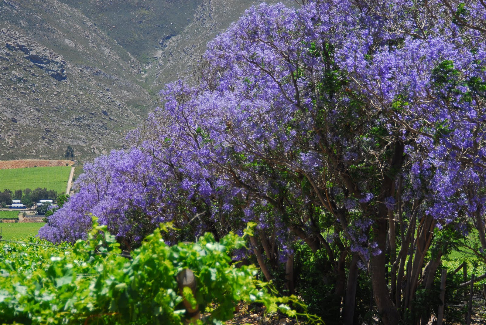
Add another striking colour to the Hex River Valley's palette: Jacaranda trees in full bloom!


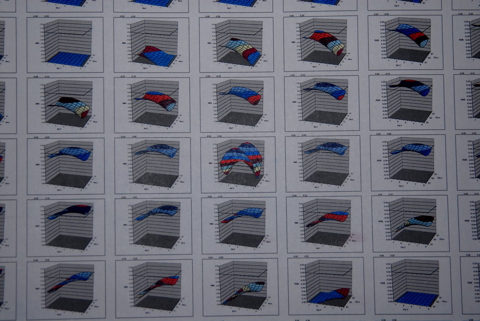
So what are we trying to achieve with this M4 alignment?  Darragh's encyclopaedic collection of Zemax simulations includes an amazing grid of Z6 (one of the two astigmatism Zernikes) surface plots that shows the effect of M4 tilt & decentre.  The perfect saddle-shaped surface (in the centre of the grid) that indicates no tilt or decentre is what we're after...  The astigmatism curves mentioned in recent posts refer to sets of wavefront measurements that slice through the Z6 surface in the X & Y directions.


Below's a zoomed in version of the central part of the grid.  Note that the vertical scale's exaggerated in the middle plot to show the saddle more clearly.


At the moment we're struggling with erratic wavefront measurements, which result in vicious spikes all over our Z6 saddle...  Naturally this is far from ideal so we've been trying Everything to track down the source of the noise.  One thing that proved marginally useful was wrapping the wavefront camera & its USB cable in aluminium foil to shield it from interference. 


Besides, it contributes to the spacey look we're going for ;)

Wednesday, November 18, 2009

Still adjusting M4!

Sadly not much excitement to report - we're still chugging away on the M4 alignment...  A recurring theme in this project is the thrill that goes with working out how to do something, followed by the slow torture of actually grinding out the process to the required tolerances!


Producing those beautiful astigmatism curves raved about in an earlier post is now part of our daily slog & not all the results generate streams of poetry...


Charl's been particularly insensitive to our misery during this phase.  Each time we make our way to/from the clean room we have to walk past him happily beavering away (making visible progress - constantly!) on the new electronics for the calibration system!


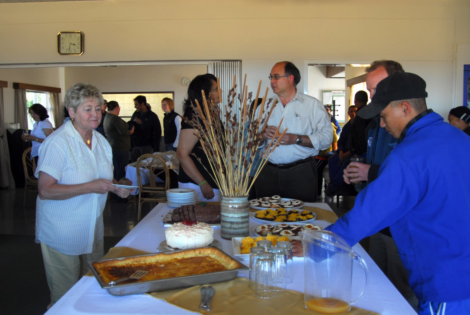
Cynthia appears to have the right idea: Retirement!!  The hostel staff put on a wonderful surprise farewell tea for her this afternoon (with the help of Linda & Glenda who hauled her up here on false pretences!).  After 44 years of service, it's the end of an era at the SAAO - all the best, Cynthia!


Thursday, November 12, 2009

1 fierce rodent, great wavefronts & a big bottle!

Ardisha found this little guy in her kitchen & brought him up to SALT before releasing him into the veld.  It's a Spectacled Dormouse, probably the same one that's been known to visit the 1.0-m dome from time to time..   Really cute but Extremely aggro - made the most amazing noises while trapped in the bucket!


Aah... free at last! Now where the hell am I??


Meanwhile, back in the clean room we were getting M4 aligned to M5 & along the way obtained our best wavefront to date: RMS = 0.05 waves!


By the end of the day we all needed to let off some steam so it was off to Eben's place for one of Ockert's potjiekos dinners (pronounced "poy-kee-kos": a traditional South African stew that's cooked in a cast iron pot over a bed of coals).


As the sun sank, the temperature plummeted & we had to get serious about survival.  Our host to the rescue with a bottle of wine to share between the 10 of us...  While that may sound conservative, the bottle was of course a Jeroboam :)


The little corkscrew that could!


Not exactly the sort of weather you'd expect in November in the southern hemisphere - apologies to our visitors from the north!


It really helps to be Eben & be absolutely immune to cold...


Thanks guys - a great evening had by all :)

Tuesday, November 10, 2009

What happens in...

Upon returning to the clean room, we found this up on the door! :)

The modifications to the tilt-adjustment mechanism on the M4 mounting ring have been made so the whole lot could be re-installed...

M4 back in the SAC, ready to be aligned - really this time! ;)