Saturday, October 31, 2009

Successful trial-alignment of M4

We've decided to make some further modifications to the steering wheel part of the M4 mount, but before taking it down to Cape Town, we spent a full day doing a trial alignment of M4 to M5.

The procedure involved finding the minimum coma position for the pinhole, then moving it off axis in X by +/- 1.5 & 1.0 mm & making wavefront measurements. Plotting the Z6 values (one of the astigmatism Zernikes) as a function of the X-offset allowed us to iteratively adjust M4 in X decentre (aiming to find a symmetrical Z6 minimum). When we could make no further improvements with X decentre, M4 was iteratively tilted in X to minimise the coma again. Next we repeated the whole procedure in the Y direction, obtaining better Z6 vs Y-offset curves & again minimising coma. A final pinhole scan in the X direction yielded the vastly better pink Z6 curve in the image below - the technique works beautifully! :)

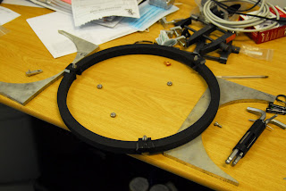
Once we got over that excitement, it was time to remove M4 & detach it from the ring that's going home with us tomorrow. Therewith my best M4 photo-op so far!

Without its ring, we had to figure out a new secure way to store M4 - 'n boer maak a plan as they say in Afrikaans. Although in this case the boer's an Irishman, but that's OK... he's one of us Africans now ;)

Off for a week now while the SALT Board Meeting takes place in Cape Town, we'll return on Monday the 9th!

Thursday, October 29, 2009

M4's Back!!

We had to tip the SAC over to extract the tube that holds the pinhole stages & light source for the M4/M5 test which needed some modifications. This afforded us a rather unusual view of the new top end...

Mods completed, the new pinhole carrier for the M4/M5 test went in, positioned at the centre of the hole in M5.

James started assembling the removable part of the new M4 mount.

The vanes needed some minor machining so it was off to the workshop with Craig for a quick milling machine tutorial.

Vanes ready - in they go...

Next, M4 itself (wearing a stylish designer cover) could be attached.

The rest of the Formula 1 car must be in this clean room somewhere?!

M4 back (very roughly) where it belongs - much fiddling to be done to get it properly aligned, but great to have a 4 mirror corrector again!

The Faro Arm was used to check the position of M4 by measuring the hole in the top of the cup.

Tuesday, October 27, 2009

Installing the new mount for M4

The necessary modifications have been made to the new M4 mount so all the gear & players came back up to SALT today to start the installation process.

To ensure the best possible fit, everything had to be drilled in situ - making for quite an eventful evening!

With the mounting blocks in place, the M4 mount's intermediate structure (popularly known as The Pizza) could go back in...

The fancy new vacuum cleaner for the clean room (aka the "Zoem Tjoeb" - pictured below with its ever-attentive handler) was soon to be put to work guzzling up the swarf.

First just spotting to mark where to drill...

Next some protection was taped in place to catch anything the vacuum cleaner might miss.

& so Craig's work-out could begin!

Not the easiest positions to work in - perhaps we should've had the guy with the drill dangling from the ceiling instead?

But with a little help from his friends, it was all over pretty quickly.

All 6 done! Great stuff :)

Saturday, October 24, 2009

All done with M5!

On our way up to the clean room this morning we got to see one of the locals - a magnificent Black Harrier - out looking for breakfast...

This week we've repeated the M5 alignment process a few times, refining the procedure & checking Everything, over & over again. Satisfied with the spot positions & the quality of the wavefront, it was time to lock the tie-rods so that the mirror can no longer translate in X & Y. All the tests were then repeated to confirm that the locking process had not disturbed the alignment.

Next we needed to measure the positions of M2 & M5 with the Faro, before tilting the SAC over to its operational angle of 37 degrees. We removed the M5 pinhole stage assembly & the M4 mounting blocks to make things a liiittle easier for the Faro jockey.

Faro'ing at angle's a whole new game - Darragh resembled a weary boxer each time he plonked down to review the data after making a 1000-point measurement of the 14 invar buttons (each done 3x, not to mention the outer diameters of M2 & M5 which are even trickier).

We left for Cape Town straight after completing the measurements, but a quick look at the data showed that M2 & M5 both moved less than 80 microns in the Y-direction & they flew in formation :)

Wednesday, October 21, 2009

New vines & a new CGH

Another week, another season in the Hex River Valley! Spring has sprung & now summer's well on its way - the vines are already looking spectacular :)

Hopes of installing the new M4 mount later this week were dashed by the discovery of a subtle slip-up by the manufacturers... Luckily this can be overcome by modifying smaller parts of the assembly so James & Craig returned to Cape Town to work on that.

In the meantime, an eagerly anticipated parcel arrived from Siberia: our huge, new CGH! It's another work of art, made more beautiful by the fact that (unlike its baby brother) it was born with a cross-hair to mark its centre...

By far the most elegant pieces of "hardware" in this entire project!

Thursday, October 15, 2009

Shimming & twiddling!

Some violent SAC interventions today! To get M5's optical axis aligned with that of M2, we had to break the epoxy locking the M5 tie rods - 1 size 10 spanner to hold the rod & another to torque the nut at each end & break the glue...

The tie rods (which attach at 1, 5 & 9 o'clock) allow adjustment of M5 in decentre. The 9 o'clock rod moves M5 in Y only, while the 1 & 5 o'clock rods move M5 in X only - provided you rotate them equal amounts in opposite directions.

There is a spherical bearing where each of the tie rods attach to M5 & this is where shims get inserted to adjust the tip & tilt of the mirror.

Combinations of shims & tie rod rotations enabled us to get the 2 points defining M5's optical axis to coincide & then these had to be made to line up with the centre of the alignment target that represents the optical axis of M2. The next 2 images show the positions of the pinhole itself & the pinhole image (both marked with a red cross-hair) with respect to the centre of the M2 target (indicated by the blue circle).

It then became an iterative process to optimise the image quality by twiddling the tie rods (using the wavefront camera's live aberration breakdown for feedback) & moving the pinhole image ever closer to the target by shimming accordingly.

Inserting & removing the shims involves lifting M5 with our soon to be patented "shimmin' tool" & slipping the required feeler-gauge in or out from under the particular spherical bearing.

By the end of a very long day we had the 3 spots lined up & M5 delivering an excellent wavefront - with that, M5 aligned with respect to M2! A fantastic way to end an epic 10 day run - off to Cape Town tomorrow for a much needed long weekend :)

Tune in next week when we hope to reinstall M4 with its improved mounting scheme!

Tuesday, October 13, 2009

Improving repeatability

Aligning M5 to M2 requires us to alternate between the wavefront camera & the alignment telescope. We found that the fold mirror used with the alignment telescope didn't always go back in a repeatable enough way so Eben came to our rescue once again.

The new scheme has the mirror attaching to the alignment telescope mount, instead of the stage assembly that the wavefront camera bolts on to - a much more reliable solution.

Monday, October 12, 2009

Chasing spots & cross-hairs

This weekend we spent a lot of time getting the alignment telescope set up on the super-structure platform. A CCD camera on the back of the alignment telescope allows us to use Francois' nifty software to determine centroids and cross-hair positions for the various points we're interested in.

The paddle mirror on the back of M2 was used to get the tip & tilt of the alignment telescope right...

& the alignment target in the hole in M2 takes care of the decentre.

With the alignment telescope ready, it was time to replace the M5 pinhole carrier & try to find the 2 points that define the optical axis of M5 (the cross-hair on top of the pinhole carrier that represents the pinhole & the image of the pinhole formed by M5).

Here's the pinhole cross-hair...

& here's the spot - the pinhole image formed by M5.

These are all the points we'll need for aligning M5 to M2 - watch this space!

Friday, October 9, 2009

Going forward again - at last...

Since our return to the clean room on Tuesday, the SALT Faro's been subjected to a number of tests before being allowed to take up its post on the aluminium ring of the NRS Simulator.

We remain satisfied with the Faro's performance so we've now established the master coordinate system on the back of M2, measured the 14 invar buttons on M2 & M5 (1000 points at a time, several times each), checked the concentricity of the alignment target within its holder (another 10000 odd points), accurately positioned the target within the hole in M2, replaced the M5 pinhole assembly & put back the super-structure of the NRS Simulator.

Without wishing to jinx anything, we should now be able to install the alignment telescope & proceed with the alignment of M5 with respect to M2. See the 31 July blog entry if, like us, you need some reminding as to how this is all supposed to work...